دنیای مهندسی سازه های دریایی
Offshore Structuresدنیای مهندسی سازه های دریایی
Offshore Structuresدرباره من
 فوق لیسانس مهندسی عمران با گرایش مهندسی سازه های دریایی علوم تحقیقات تهران
bijan_4823t@yahoo.com
I am Bijan Mohammadi, Education: MS.c Civil Engineering- Marine Structures Engineering
For more information on the bottom left of the screen authorities to MY resume
www.linkedin.com
ادامه...
فوق لیسانس مهندسی عمران با گرایش مهندسی سازه های دریایی علوم تحقیقات تهران
bijan_4823t@yahoo.com
I am Bijan Mohammadi, Education: MS.c Civil Engineering- Marine Structures Engineering
For more information on the bottom left of the screen authorities to MY resume
www.linkedin.com
ادامه...
Frontiers in Offshore Geotechnics II,Susan Gourvenec and David White,CRC Press,2010
این کتاب درباره سرحدهای ژئوتکنیک فراساحلی می باشد، که دارای 939 صفحه است مجموعه ای از مقالات ارسالی به دانشگاه غربی استرالیا می باشد که توسط نویسندگان جمع آوری شده است. با این عناوین
Frontiers in Offshore Geotechnics II,Susan Gourvenec and David White,CRC Press,2010
The titles
This file is password
Password: CE-MS MS.c Bijan Mohammadi
All text and change the color to use to download it
دانلود / Download کلمه عبور/Password

1 Keynotes
A systematic approach to offshore engineering for multiple-project developments in geohazardous areas
Recommended best practice for geotechnical site characterisation of cohesive offshore sediments
Gulf of Guinea deepwater sediments: Geotechnical properties, design issues and installation experiences
Geotechnics for subsea pipelines
Axial and lateral pile design in carbonate soils
New frontiers for centrifuge modelling in offshore geotechnics
Risk and reliability on the frontier of offshore geotechnics
2 Geohazards and gas hydrates
Neotectonic deformation of northwestern Australia: Implications for oil and gas development
Deepwater Angola part I: Geohazard mitigation
Deepwater Angola part II: Geotechnical challenges
Shallow gas hazard linked to worldwide delta environments
Analysis of submarine flow slides in fine silty sand
Hydrate dissociation around oil exploration infrastructure
An investigation of past mass movement events in the West Nile Delta
Deformation of seabed due to exploitation of methane hydrate reservoir
3 In situ site characterisation and pore pressure measurement
A site investigation strategy to obtain fast-track shear strength design parameters in deep water soils
Enhancement of the ball penetrometer test with pore pressure measurements
Laboratory free falling penetrometer test into clay
Offshore sediment overpressures: Overview of mechanisms, measurement and modeling
Angolan deep water soil conditions: GIS technology development for sediment characterization
Strength measurement in very soft upper seabed sediments
CPT in polar snow – preliminary observations
Parametric study of a free-falling penetrometer in clay-like soils
The future of deep water site investigation: Seabed drilling technology?
Mini T-bar testing at shallow penetration
Piezometer installation in deep water Norwegian Sea
Luva deep water site investigation programme and findings
Investigations into novel shallow penetrometers for fine-grained soils
Seabed drilling vs surface drilling – a comparison
4 Soil characterisation and modelling
Rheological behaviour of soft clays
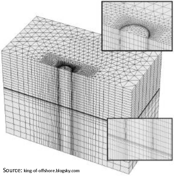
A three-dimensional finite element study of the direct simple shear test
Repeated loading and unloading of the seabed
A new interpretation of the simple shear test
Physical modelling of the crushing behaviour of granular materials
New evidence for the origin and behaviour of deep ocean ‘crusts’
Soil unit weight estimated from CPTu in offshore soils
Strain rate dependent simple shear behaviour of deep water sediments in offshore Angola
Simplified calibration procedure for a high-cycle accumulation model based on cyclic triaxial tests on 22 sands
Understanding cyclic loading behavior of soil for offshore applications
5 Shallow foundations
Observations of shallow skirted foundations under transient and sustained uplift
Numerical study of grillage foundations on sand under combined VHM loading
The vertical bearing capacity of grillage foundations in sand
Behaviour of skirted footings on sand overlying clay
Numerical study of piping limits for suction installation of offshore skirted foundations and anchors in layered sand
Shallow foundation performance in a calcareous sand
A numerical study of the vertical bearing capacity of skirted foundations
The effect of torsion on the sliding resistance of rectangular foundations
Foundation design challenges of the MCR-A skirted gravity platform
Constructing breakwater with prefabricated caissons on soft clay
6 Piled foundations
Simplified analysis of laterally loaded pile groups
Behavior of piles under combined lateral and axial loading
Investigations on the behavior of large diameter piles under cyclic lateral loading
BP Clair phase 1 – Pile driveability and capacity in extremely hard till
Photoelastic investigation into plugging of open ended piles
Soil-pile interaction during extrusion of an initially deformed pile
BP Clair phase 1 – Geotechnical assurance of driven piled foundations in extremely hard till
Pile driving experiences in Persian Gulf calcareous sands
FLAC3D analysis on soil moving through piles
Cyclic loading of barrettes in soft calcareous rock using Osterberg cells
Shaft capacity of drilled and grouted piles in calcareous sandstone
Numerical analysis of mudmat contribution to capacity of piled offshore platforms
Simplified numerical model for analysis of offshore piles under cyclic lateral loading
Centrifuge modelling of rapid load tests with piles in silt and sand
Field measurements on monopile Dolphins
Behaviour of driven tubular steel piles in calcarenite for a marine jetty in Fujairah, United Arab Emirates
CPT-Based design method for axial capacity of offshore piles in clays
7 Foundations for renewable energy
Evaluation of pile capacity approaches with respect to piles for wind energy foundations in the North Sea
Installation of suction caissons for offshore renewable energy structures
Lateral behaviour of large diameter monopiles at Sheringham Shoal Wind Farm
Centrifuge modelling of offshore monopile foundation
Gravity based foundations for the Rødsand 2 offshore wind farm, Denmark
Geotechnics for developing offshore renewable energy in the US
Engineering issues for fixed offshore wind turbines on Lake Michigan Mid Lake Plateau, USA
Centrifuge model tests on piled footings in clay for offshore wind turbines
Design of monopile foundations in sand for offshore windfarms
Experimental evaluation of backfill in scour holes around offshore monopoles
An investigation of the use of a bearing plate to enhance the lateral capacity of monopile foundations
Optimizing site investigations and pile design for wind farms using geostatistical methods: A case study
Towards the FE prediction of permanent deformations of offshore wind power plant foundations using a high-cycle accumulation model
Cyclic accumulation effects at foundations for offshore wind turbines
Study on soil-structure interaction of suction caisson by large-scale model tests
8 Jack-up units
Simplified VH equations for foundation punch-through sand into clay
Characterisation of undrained shear strength using statistical methods
Centrifuge modelling of spudcan deep penetration in multi-layered soils
A probabilistic approach to the prediction of spudcan penetration of jack-up units
An assessment of jackup spudcan extraction
3D FE analysis of the installation process of spudcan foundations
Undrained bearing capacity of deeply embedded foundations under general loading
9 Anchoring systems
Trajectory prediction for drag embedment anchors under out of plane loading
Setup following keying of plate anchors assessed through centrifuge tests in kaolin clay
Seismically-induced displacements of a suction caisson in soft clay
SEPLA keying prediction method based on full-scale offshore tests
Set-up of suction piles in deep water Gulf of Guinea clays
Centrifuge testing of suction piles in deep water Nigeria clay – Effect of stiffeners and set-up time
Numerical FEM and laboratory study of the bearing capacity factor Nc for plate anchors
Caisson capacity in clay: VHM resistance envelope – Part 2: VHM envelope equation and design procedures
Installation and in-place assessment of drag anchors in carbonate soil
Caisson capacity in clay: VHM resistance envelope – Part 1: 3D FEM numerical study
Numerical investigation of the behaviour of suction caissons in structured clays
Cyclic moment loading of suction caissons in sand
10 Pipelines and risers
Multidirectional analysis of pipeline-soil interaction in clay
Geotechnical challenges for deep water pipeline design – SAFEBUCK JIP
Large deformation finite element analysis of vertical penetration of pipelines in seabed
Implementation of geotechnical techniques in the analysis of pipeline response
Lateral soil resistance to an untrenched pipeline under the action of ocean currents
Vertical cyclic testing of model steel catenary riser at large scale
Kupe gas project pipeline – optimisation of discrete rock berm design shore approach
Model test studies on soil restraint to pipelines buried in sand
Pipe-soil interaction on clay with a variable shear strength profile
Sweeping behaviour of shallowly-embedded pipeline during cyclic lateral movement
Advanced nonlinear hysteretic seabed model for dynamic fatigue analysis of steel catenary risers
Mobilization distance in uplift resistance modeling of pipelines
Theoretical, numerical and field studies of offshore pipeline sleeper crossings
Observations of pipe-soil response from the first deep water deployment of the SMARTPIPE®
11 Trenching, ploughing, excavation and burial
Influence of object geometry on penetration into the seabed
Investigation into the effect of forecutters on plough performance
State-of-the-art jet trenching analysis in stiff clays
Numerical modelling of soil around offshore pipeline plough shares
Anchor–chain–rock fill–soil interaction: Evolution of design methods
Development of a jet trenching model in sand
12 Design and risk
Structural factors affecting the system capacity of jacket pile foundations
The new API Recommended Practice for Geotechnical Engineering: RP 2GEO
Comparison of ISO 19901-2 and API RP 2A seismic design criteria for a site in the Caspian Sea, Turkmenistan
Animation Single buoy mooring or single point mooring with full details/انیمیشن بویه مهاری تک با جزئیات کامل
این انیمیشن طریقه نصب و راه اندازی بویه مهاری تک یا مهاری تک نقطه را جزئیات کامل نشان می دهد.
This animation single buoy mooring or single point mooring mode installation show detail.


متاسفانه اسمی که برای این سازه سازمان بنادر دریا نوردی در آیین نامه کارهای دریایی ایران و همچنین واژه نامه سازه های ساحلی معاونت برنامه ریزی و نظارت راهبری رییس جمهوری نشریه شماره 628 انتخاب کردن به نظر دارای مشکلات است اگر من این سازه ترجمه می کنم با تمام واژه نامه فارسی باشد اگر من اسمی را برای سازه انتخاب می کنم با توجه به کارکرد آن انتخاب می کنم نه که دور هم بشنیم مهاربند بکنم مهاری بعدش هم خود این واژه نامه را به انگلیسی ترجمه کنیم یک چیز دیگر باشد هرچند واژه یک سازه فراساحلی است.
Buoy یعنی جسم شناور، روآبی، رهنما شناور اگر من برای این سازه اسم انتخاب می کردم اسم فعلی نبود.
.JPG)
.JPG)
بویه مهاری تک یا مهاربند تک نقطه ای چیست؟
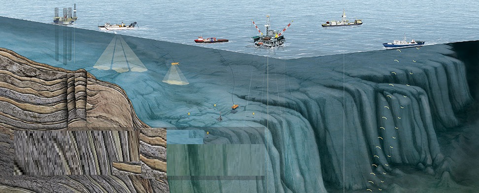
این سازه که در عمق های بالای 15 متری نصب می شود عمومآ برای تخلیه و بارگیری نفت و گاز به عنوان یک پایانه نفتی برای نفتکش ها مورد استفاده قرار می گیرد. هدف اصلی این سازه شناور انتقال مایعات و گاز از ساحل به فراساحل می باشد . همانطور که در این انیمیشین ملاحظه خواهید کرد در کنار سکوهای نفتی از این سازه برای بارگیری استفاده می شود .
نکته مهمی که باید در طراحی زنجیر مهاری ها مورد استفاده باید قرار گیرد سازه زنجیر مهاری باید با روش مناسب به گونه ارزیابی گردد که زنجیرها قادر به نگهداری جسم شناور در محل خود به طور ایمن تحت اعمال بزرگترین بار باشد .بزرگترین بار نیروهای خارجی که در طراحی نقش مهمی دارند. برای نیروهای خارجی ، از بین ترکیب بارهای زیر که بزرگترین نیروی کل را ارایه دهد، استفاده می گررد.
1- نیروی عکس العمل ضربه گیر و نیروی جریان کهکشان و مهکشان (جزر ومد)
2- نیروی طناب مهاری کشتی و نیروی جریان کهکشان و مهکشان
3- نیروی موج و نیروی جریان کهکشان و مهکشان

بویه مهاری از نظر سازه ای به سه دسته تقسیم می شود که شامل :
1- وزنه ای 2- لنگر زنجیری 3- ترکیب وزنه و لنگر زنجیری می باشد.

جزئیات عمومی بویه های مهاری/Details of mooring buoy

What is a Single buoy mooring(SBM) Or Single point mooring (SPM
A Single buoy mooring (SBM) (also known as single point mooring or SPM) is a loading buoy anchored offshore, that serves as a mooring point and interconnect for tankers loading or offloading gas or liquid products
SPMs are the link between geostatic subsea manifold connections and weathervaining tankers. They are capable of handling any size ship, even very large crude carriers (VLCC) where no alternative facility is available
Its constituent companies started their offshore activities in the early 1950s and SBM subsequently became a pioneer in single point mooring (SPM) systems. The Single Point Mooring concept originated in the 1960´s as a solution to the problem of transferring crude oil from an onshore reception facility or refinery into very large crude carriers oil tankers
The main purpose of the buoy is to transfer liquids between onshore or offshore facilities and the moored tanker

There are a number of types of facilities presently used to load or off-load tankers in open water. These include Sea Islands; spread moorings, single point mooring structures and single buoy moorings. Of these, the single buoy mooring has been most frequently installed to service today's very large tankers
The popularity of the single buoy mooring stems from the fact that it can be installed at almost any offshore location where deep water is relatively close to shore. Water depth can be selected to suit any required tanker draft. Nearly the only limitation is that the buoy must be installed a safe distance from shoal water that could constitute a danger to the tanker while mooring or unmooring
The submarine pipeline and single buoy mooring system, shown schematically in Figure 1, consist of a submarine pipeline from the onshore tank farm, a bottom manifold at the end of the submarine pipeline, underbody hose connecting the bottom manifold with the buoy, the buoy itself, and one or more strings of floating hose between the buoy and the tanker. When moored to the buoy, the tanker can rotate or weathervane to minimize the combined force of wind, wave and current
10( (2).jpg)
The submarine pipeline and single buoy mooring system was first put into use in 1959. Since that time there has been a continuous increase in the number of single buoy mooring installations around the world. (Figure 2
10( (3).jpg)
این آمارها برای سال 1970 می باشد/ The statistics is for 1970
Recent tabulations show a total of 46 installations located in 23 different countries (Figure 3
Most of the installations put into service since 1965 have been designed for 100,000 dwt tankers or larger. Early next year a buoy designed to service 350,000 dwt tankers will be commissioned
10( (1).jpg)
During the decade that the single buoy moorings have been in use there have been only a few relatively small oil spills associated with their operation. Because of the increasing popularity of the submarine pipeline and single buoy mooring system and its use for ever large tankers, it is extremely important that designs be adequate and operation be carefully controlled
یک نگاه به کاربرد بویه مهاری تک که در منطقه خلیج فارس قرارداد.
Use single buoy mooring contract in the Persian Gulf region

.jpg)
Major Saudi Arabian Offshore Oil Fields. Oil export terminals are indicated with reddish dots
The largest oil exporting terminal in the world is located on the Ras Tanura peninsula and is capable of loading over 5 million barrels of oil per day onto tankers moored on one of two T-shaped terminals (small vessels only) or on one of a cluster of four Sea Islands located offshore in deeper water. The limit for tankers berthed at the Sea Islands is 550,000 dwt (dead-weight tons
.jpg)
The Al Juaymah Offshore Terminal is located to the northwest of Ras Tanura, just east of the Qatif oil field as shown below. The Qatif field lies both on and off shore, with several offshore platforms positioned to drill and maintain offshore wells. Oil is loaded onto tankers from Single Point Moorings (SPMs) anchored in deeper water such that larger ships can be handled (up to 700,000 dwt). It has been in operation since 1974. The Al Juaymah complex also includes a pier from which liquified natural gas (LNG) is loaded onto ships
.jpg)
Oil is similarly delivered from shore in underwater pipeline to a platform, distributed to the SPMs and then transferred to the tanker via large flexible hoses connecting them to the SPM. There are six SPMs at Al Juaymah, which can theoretically output six million barrels per day and has been in operation as early as the 1970s. In a 2005 Google Earth satellite image, I can only find two SPMs, although others might be present in low resolution images
.jpg)
Shown below is a close up of the darker tanker from above receiving oil. There are two "hoses" attached to this tanker, whereas there are three attached to the other. I haven't found anything recent on loading rates, although SPE 4013-MS suggests that each (in the late 1970s) was designed for a flow of at 130,000 barrels per hour but averaged only half that in practice


