دنیای مهندسی سازه های دریایی
Offshore Structuresدنیای مهندسی سازه های دریایی
Offshore Structuresدرباره من
 فوق لیسانس مهندسی عمران با گرایش مهندسی سازه های دریایی علوم تحقیقات تهران
bijan_4823t@yahoo.com
I am Bijan Mohammadi, Education: MS.c Civil Engineering- Marine Structures Engineering
For more information on the bottom left of the screen authorities to MY resume
www.linkedin.com
ادامه...
فوق لیسانس مهندسی عمران با گرایش مهندسی سازه های دریایی علوم تحقیقات تهران
bijan_4823t@yahoo.com
I am Bijan Mohammadi, Education: MS.c Civil Engineering- Marine Structures Engineering
For more information on the bottom left of the screen authorities to MY resume
www.linkedin.com
ادامه...
اجرایی عملیات بالانس در کار ژئوتکنیک/ Geotechnical work balance operations
این فیلم عملیات بالانس در کار ژئوتکنیک نشان می دهد.
The film shows the balance in the geotechnical work

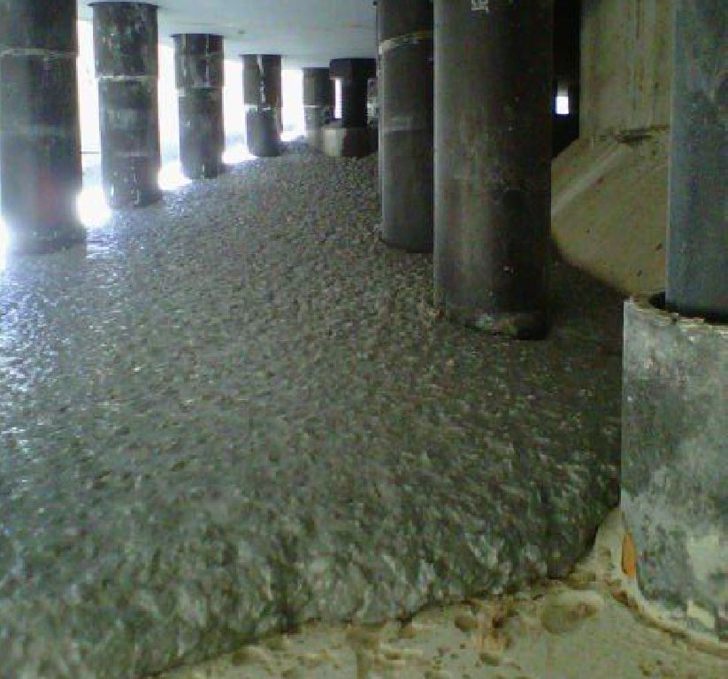
بیشک یکی از روشهای بهبود خواص مکانیکی خاک افزایش تراکم آن است. روشهای مختلفی برای این کار وجود دارد، یکی از این روشها که بسیار سریع و ارزان میباشد (البته در مناطق غیرمسکونی) تراکم از طریق انفجارهای کنترل شده است. در پایان این فیلم با توجه به اینکه امواج تولید شده در اثر انفجار مشابه اعمال نیروی زلزله است، لذا جوشش ماسه به وضوح دیده میشود
فیلم نحوه آزمایش نفوذ مخروط با ماشین/Video of cone penetration test with car
این فیلم نحوه آزمایش نفوذ مخروط را نشان می دهد.
This is Video of cone penetration test
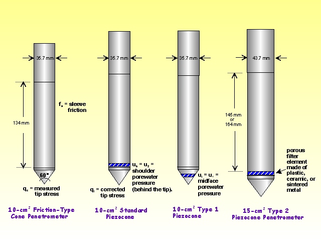
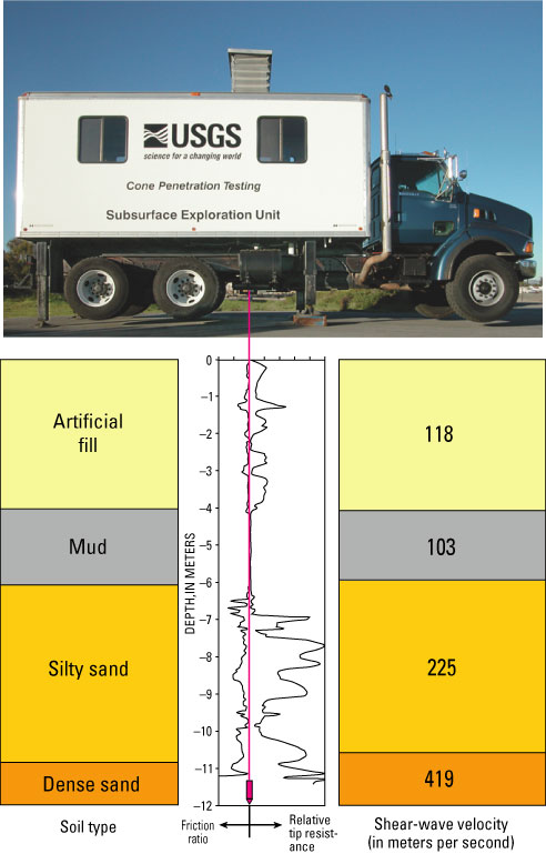
The cone penetration or cone penetrometer test (CPT) is a method used to determine the geotechnical engineering properties of soils and delineating soil stratigraphy. It was initially developed in the 1950s at the Dutch Laboratory for Soil Mechanics in Delft to investigate soft soils. Based on this history it has also been called the "Dutch cone test". Today, the CPT is one of the most used and accepted in soil methods for soil investigation worldwide.
The test method consists of pushing an instrumented cone, with the tip facing down, into the ground at a controlled rate (controlled between 1.5 -2.5 cm/s accepted). The resolution of the CPT in delineating stratigraphic layers is related to the size of the cone tip, with typical cone tips having a cross-sectional area of either 10 or 15 cm², corresponding to diameters of 3.6 and 4.4 cm. A very early ultra-miniature 1 cm² subtraction penetrometer was developed and used on a US mobile ballistic missile launch system (MGM-134 Midgetman) soil/structure design program in 1984 at the Earth Technology Corporation of Long Beach, CA
Cone Penetration Testing (CPT) is used to identify subsurface conditions in the upper 100 ft of the subsurface. The USGS CPT uses a 23-ton truck to push a “cone” into the ground. The weight of the truck is partially supported by both the tip of the cone and the sleeve of the cone. The “tip resistance” is determined by the force required to push the tip of the cone and the “sleeve friction” is determined by the force required to push the sleeve through the soil. The “friction ratio” is the ratio between sleeve friction and tip resistance, measured as a percentage. Soil type and thereby resistance to liquefaction can be inferred from these measurements

کاربرد میکرو بالانس در ژئوتکنیک /Application Micro balance in Geotechnical

میکرو بالانس
میکرو بالانس تکنولوژی انفجار استفاده شده است که در زمان ساخت جاده ها، مجموعه های صنعتی، بنادر، فرودگاه ها، موج شکن، سدها حفظ و ساختمان های دیگر. این کار باعث می شود بهبود حجم زیادی از خاک ضعیف در یک زمان کوتاه و همچنین تضمین دریافت قدرت اولیه در مقدار پارامترهای است.
میکرو بالانس تکنولوژی انفجار بکاربردن انرژی حاصل از انفجاری کوچک که باعث می گردد جابچای سطح روی و زیر زمینی زمین می گردد.

MICROBLASTING
Micro blasting technology is used when constructing roads, industrial objects, ports, airports
breakwaters, retention dams and other buildings. It enables improvement of large volumes of weak soil in a short time as well as guarantees receiving first rate strength parameters
Micro blasting technology employs the energy of small explosive charges placed on surface, laid Underground or just above the bottom of the water body
Loose non-cohesive soil improvement (DDC – Deep Dynamic Compaction)
Microblasting causes saturated subsoil compaction. Thanks to excessive pressure in the soil pores previous structure of non-cohesive soil is destroyed and after a momentary liquefaction the particles settle in a denser configuration while water filters up to the surface. Repeating of blastings in series supports these processes. Microblasting may be successfully
applied underwater as well as on land
Saturated organic soil improvement (DDR – Deep Dynamic Replacement)
Microblasting technology enables significant acceleration of the consolidation process through formation of sand columns which act as drain channel and – at the same time – strengthen the subsoil. Explosive charges are installed in boreholes and detonated in a couple of specially designed sequence series
Additional layer of non-cohesive material, e.g. sand is temporarily liquefied into caverns (cavity formed as a result of the explosion) creating sand columns of big diameter (up to 2 meters
Safety
The microblasting technology is not hazardous to human life or health as well as neighbouring buildings
provided the soil improvement procedure is properly planned, carefully designed and neatly performed by qualified and experienced contractors and the right distance from the explosion site is kept (30-50) meters
Advantages
Efficiency
improvement of up to 10 000 000 m3 of subsoil per month
reduction of soil settlement in terms of live load to a level which is significantly lower than
specified by both Polish and foreign constructing standards
the depth of ground to be improved is theoretically unlimited
Effectivness
attaining high values of improved subsoil’s strength parameters
continuous quality monitoring of subsoil’s improvement
Rate of performance
much faster consolidation of subsoil in comparison to other soil improvement technologies
Economical aspect
low cost of performance in comparison to other soil improvement methods
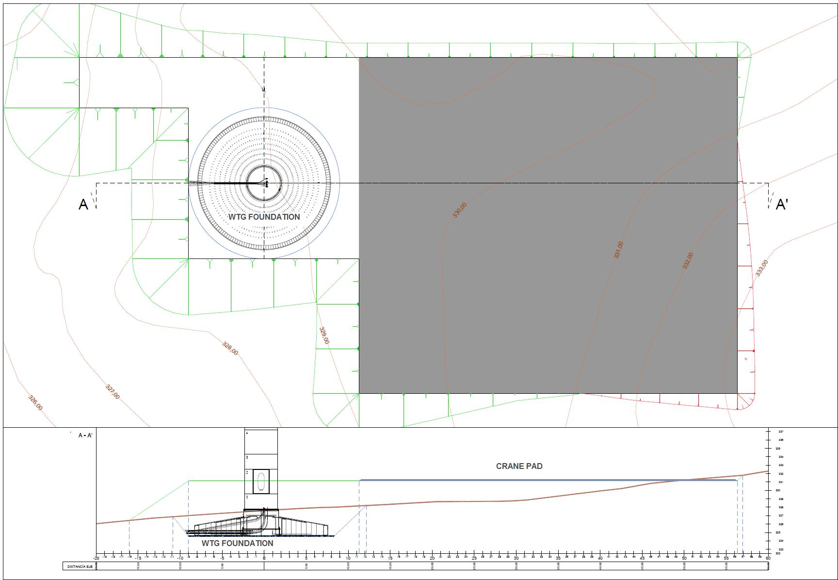
طراحی و اجرای فونداسیون توربین بادی/Design & implementation of wind turbine foundation
این فیلم نحوه طراحی و اجراء فونداسیون توربین بادی را نمایش می دهد.
This is Design & implementation of turbine foundation
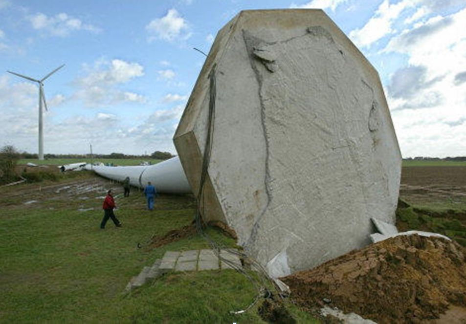
هندسه نصب توربین های بادی خشکی
پس از عبور هوا از اولین توربین بادی به دلیل اینکه هوا با پدیده انفجار مواجه می شود توربین های بادی بهتراست به صورت زیگزاگی نصب شوند تا بیشترین راندمان را داشته باشند. لذا فاصله بهینه هر توربین از توربین مجاورش حدود 3 الی 3.5 برابر قطر روتور توربین مجاورش است.
هرچند این فیلم کامل نبود و نواقصی مهمی هم دارد که در ماه آینده درباره آن اشاره خواهم کرد

Geometry installed onshore wind turbines
After the air passes through the first wind turbine because the air is faced with the phenomenon of the explosion of wind turbines should be installed in a zigzag to have maximum efficiency. The optimum distance is about 3 to 3.5 times the diameter of the turbine adjacent turbine rotor is nearby.
Although the film was not complete and there are significant defects noted that next month it will
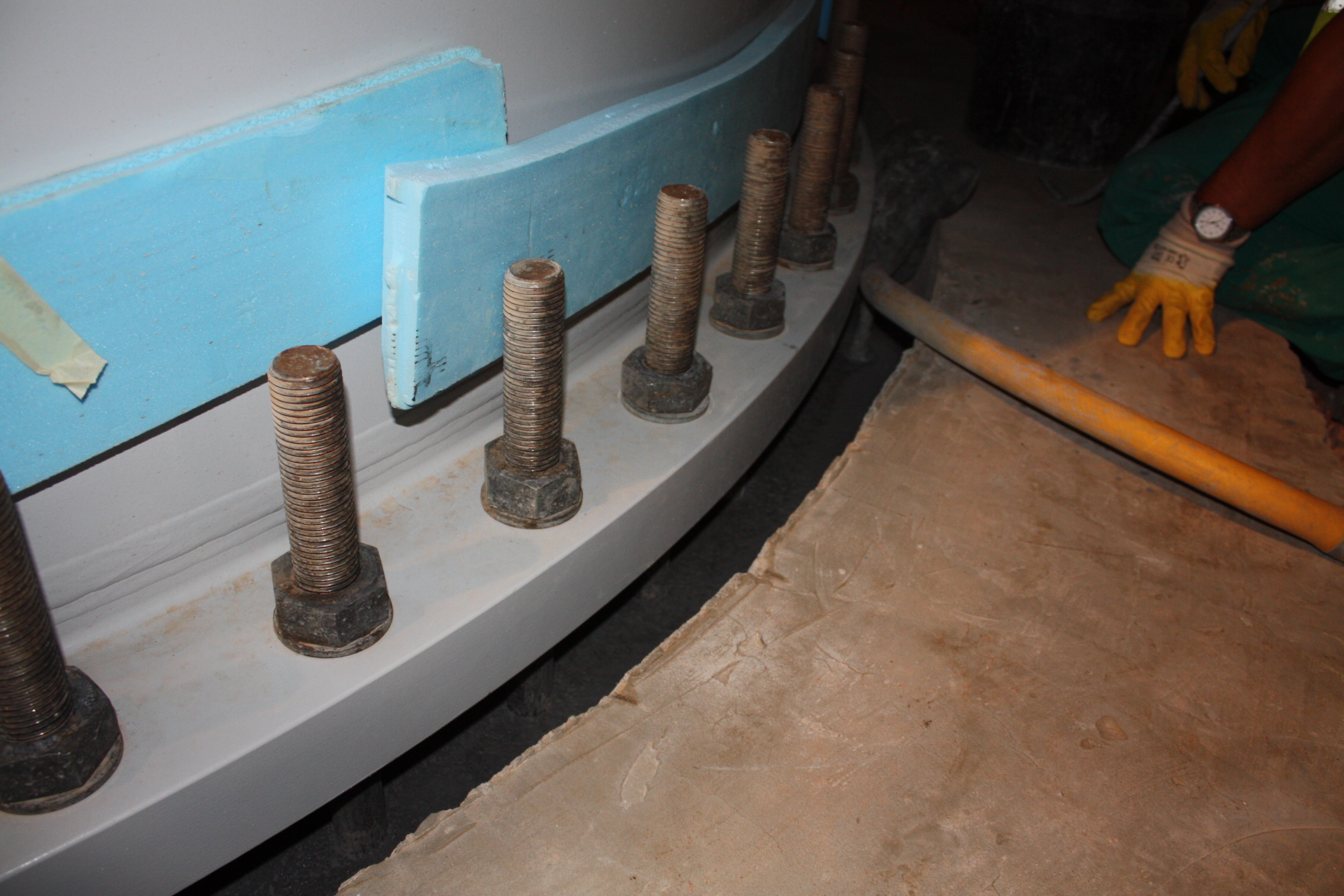
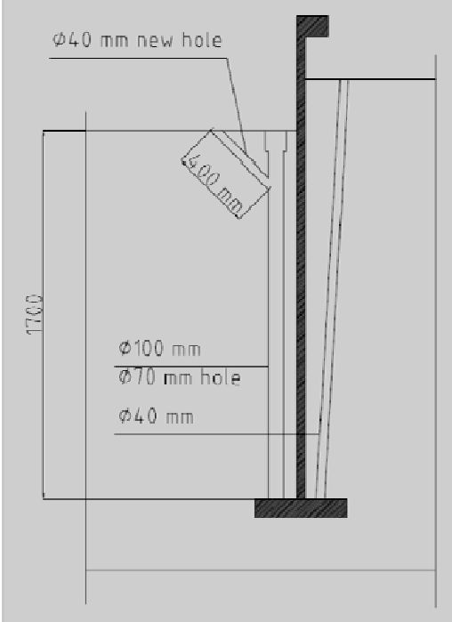
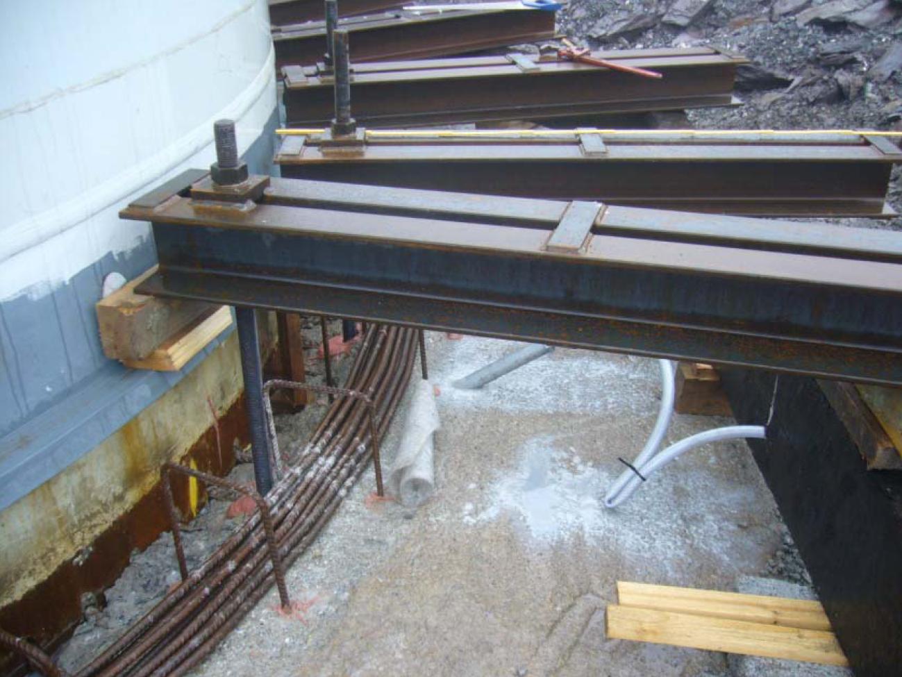
نحوه اجرای و طراحی این فنداسیون های بستگی به شرایط موقعیت و جنس زمین دارد که در ماه های بعدی درباره آن شرح می دهم این فنداسیونهای 4 حالت مختلف دارد